
This page is about the first version of Drezno. There was a revision in 2023, Drezno II, which has more stability/less noise, and calibrated slider ranges. Many of the tips here should still work, but some rely on the module’s inherent noisiness. It’s also possible that your own case/power/other nearby equipment will lead to less, more, or totally different noise. It’s all part of the adventure of Eurorack 🙂
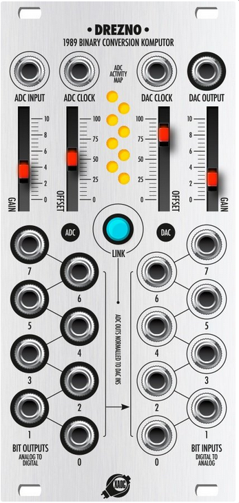
Drezno is the “master” module in Xaoc Devices’ Leibniz Binary System series of Eurorack modules. It consists of an 8-bit ADC (analog-digital converter) with an analog input and an output jack for each bit, paired with an 8-bit DAC (digital-analog converter) with an input jack for each bit and an analog output. It has an internal, approximately 2Mhz clock which can be overridden individually for the ADC and/or DAC with an external input, and each side has sliders for the gain and offset.
The “Leibniz Bus” is a ribbon cable on the back panel that carries a clock and 8 data bits. If you have no other Leibniz modules, you’ll just leave the included cable connecting the ADC to the DAC. The Link button enables the DAC bus inputs, but the panel inputs always override them. In my patches below, assume Link is enabled if I don’t specify otherwise.
I’m not going to cover other Leibniz modules here, as I don’t have any of them any more. I find Drezno alone is quite powerful, and recommend trying it by itself before jumping into other modules.
(There’s a new alternate entry point to the Leibniz system, the Berlin. Instead of an ADC, it features a nice wide-range numeric oscillator and synchronized clock, perfectly suited to drive Jena as well as some intriguing combinations with other modules. It’s a very different approach from Drezno, but also kind of exciting.)
I highly recommend reading Xaoc’s official manual for Drezno. I’m not going to explain much theory here, I’m simply sharing some notes about using the module in practice.
The Bits!
The “low bits” or LSB (least significant bits), are the ones with the lowest numbers and are physically lower on the panel. The “high bits” or MSB (most significant bits) have higher numbers and are higher on the panel. Should be easy to remember.
In general:
- low bits are prone to more frequent changes (or generally higher-frequency outputs), represent smaller numeric values, and are more susceptible to noise and instability.
- high bits tend to change less frequently, represent larger numeric voltages, and tend to be more stable.
- remember that the high bits are only “more” in the binary numeric system — the outputs have the same +5V voltage range.
Scope It Out
Of all the modules I’ve used, Drezno is the one that benefits the most from an oscilloscope. Preferably one with at least two traces, such as the Jones O’Tool+ or Mordax Data. These modules are super useful for learning the behavior of a module or a tricky patch, for calibrating levels and frequencies in general. With Drezno there’ll be times when you want to compare input and output voltages, and/or the timing of gate outputs compared to the input signal. O’Tool+ is the module I’ve own the third-longest (shy only of Rings and Kermit mk2) and I’ve never once considered setting it aside to use the space for something else.
Levels are important…
The settings of the input Gain and Offset have an enormous impact on the behavior of Drezno. “Ideally” you want the range of your input signal to correspond to a numeric 0 to 255 range in the ADC output. If your signal is bipolar, 0V should correspond to 128 (bit 7 on, all other bits off); if unipolar and balanced, 0V should be 0 and your highest possible voltage to 255. With that range, you’re making the most of the available digital headroom, without clipping your signal.
In practice, it’s very unlikely you’ll get this exactly right, and that’s not your fault.
For this part, assume the input is something symmetrical and bipolar, like a sine wave, and is going at low-mid audio rate. Let’s say the modules’ 8 yellow LEDs are all lit, albeit not at the same brightness — they are cycling faster than the eye’s ability to detect flickering. This is no guarantee you’re in the 0-255 range, it just means you’re going over 128 a fair amount of the time. The LSBs are likely to flip on and off a lot even when you’re not especially close to 0.
- Patch your signal through the ADC input and DAC output, and compare the input and output signals on a scope. Adjust the sliders so that the input and output levels match without shrinking, clipping, or being offset. On my module, I find that bipolar signals seem to like about 7,10,0,10. A stronger or weaker signal may call for more or less input gain, though — you generally want the gain to be as high as it’ll get without clipping. (This is likely to be different on the Drezno II since it’s doing something different with level calibration.)
- Now try patching the ADC Bit 7 output to the scope. If your signal is spanning most of the 0-255 range, this bit will be on whenever the signal is in its top half, and off otherwise.
- Try a unipolar looping envelope instead of a bipolar sine. If I do that with my 7,10,0,10 settings, what I see Bit 7 is on most of the time. That’s not ideal, because it means the values are mostly in the 128-255 range. So, lower the input offset to 0 and adjust the output offset and gain sliders as needed. On my unit, I find that 8,0,8,5 is about right for unipolar signals (but again, more gain might be called for with weaker signals).
…or are they?
You might intentionally choose “bad” settings for effect.
- Intentionally using less headroom can be similar to bitcrushing. You’re generally not going to run audio through Drezno unless you want it to be dirtier anyway…
- Intentionally clipping is a tried and true distortion method that also can make more interesting CV shapes.
- Intentionally introducing a DC offset can also be a neat thing if you’re going into other distortion afterward.
But you’ve got no CV control over the gain and offset, so you may need to rely on external VCAs or other utilities to do your clipping and offsetting.
Also, there are plenty of applications for Drezno where you care more about the bit outputs from the ADC than the reconstruction in the DAC. For that you’ll probably just want to tweak the input sliders for the coolest results regardless of accuracy.
Audio Processing Patches
Drezno is a champ at lo-fi-izing audio signals. Truthfully I use it for this more than anything else. Merely passing a signal through it will, at best, degrade it to 8 bits and introduce some noise, which is pleasantly noticeable without being too extreme.
Clocking Patches
- Plugging in an external oscillator — preferably one capable of going to around 40Khz — to either of the clock inputs will downsample your audio. You could also use white noise for your clock, or a mix of two oscillators or an oscillator and noise.
- Using one of the ADC’s own bit outputs to clock the DAC (not the ADC, you’ll just freeze it) can have radical effects, depending on the input signal’s nature and dynamics. (You can combine this with clocking the DAC.)
- Using two high-rate clocks for the ADC and DAC tuned a bit differently can be pretty neat too.
- Using a clock (or two) related to the oscillator you’re feeding to the ADC input can be lovely. A complex oscillator or something like Just Friends is good for this.
Example 1: Blades self-oscillating, through Natural Gate. Dry for the first 8 seconds, then through Drezno. At :15, the DAC is clocked from cDVCA, with the frequency slowly swept downward. At :45, DAC is clocked by noise from Morbus Legio, with its rate gradually lowered. At :59, ADC Bit 0 is patched to the DAC clock input, repatching progressively to higher bits (brief silences are when a patch cable is connected to the clock input but not the other end).
Example 2: Sine wave from Blades through Drezno, with DAC clocked by cDVCA. ADC bit 2 FMs cDVCA. After exploring some frequency knob settings on the clock, different bits are patched to the FM input.
Example 3: Make Noise Function acting as a triangle wave oscillator into Drezno. First with the internal clock, then at :08 clocked by bit 2. Input gain and offset are adjusted to show the different waveshapes that result as the bit pattern changes.
Example 3b (I didn’t want to renumber everything after recording this out of order): Just Friends’ Mix output into ADC, and 5N and 6N outputs to the ADC and DAC clocks. Intone knob is turned a few times, changing the ratio between outputs. At the end the clocks are too slow to reasonably send the audio signal.
Bit Patches
You have four options for reducing the bit depth on Drezno:
- Lower the input gain and increase the output gain to compensate. You may have to boost the output more with an external module. You’ll also amplify any other noise and interference along the way (part of the charm, right?)
- Insert dummy cables, starting at the LSB and working your way upward to “decimate” the bits. (Patch them to a 0V reference if you want to be sure they’re 0 and not “floating” at 1.)
- Turn off the Link button, and patch explicitly starting at the MSB and working your way down to increase the bit depth.
- With Link off, patch ADC bit 0 to DAC bit 1, ADC 1 to DAC 2, and so on (leaving DAC 0 empty). You can skip more bits if you like. This generally quiets the output level and offsets it downward, while lowering the resolution.
Other tricks:
- Instead of just zeroing bits, you can rearrange them. Remember the general rule: low bits change quickly, high bits count for more level. Experiment with different combos to see what happens, and watch the results on a scope if you can to get a more solid feel for what’s happening.
- Plug a different oscillator into one of the DAC inputs. The higher the bit, the more extreme the effect.
- You’d think that Boolean logic modules would be a natural fit to manipulate bits, but in practice, I mostly don’t find them that exciting. However, combining ADC bits with tempo-synced clocks or gate patterns can be a bit more fun. If you don’t have logic modules, a regular VCA works as an AND gate and a mixer as an OR.
- Feedback-patch the DAC’s analog output to one of the bits (probably not 7, but lower ones can be interesting).
- Patch noise into one or more of the DAC bit inputs (probably a low one).
- Mystic Circuits Ana 2 is a nice partner for Drezno. Patch your dry audio signal into both the ADC and one of Ana’s inputs, and patch either a bit output or the DAC output into another input on Ana. Monitor one (or more) of Ana’s outputs.
- Try processing one of the ADC bits with an allpass filter (such as Instruo DAPF) before feeding it into the DAC. Other filters can also have some effect, but what you want is the phase shift.
- Process one of the bits with a clock divider/multiplier, gate sequencer, or clockable LFO that can handle audio rates. Using a different bit on the input and output can be interesting here.
- Feed an oscillator to the ADC, and use a bit output to FM, PM or modulate some other parameter on the oscillator. This is a feedback loop that can be chaotic, depending. Alternately, you could use the bit to modulate something else (a filter, wavefolder, etc. — allpass is a good choice here too).
- Instead of feeding the ADC directly, patch multiple oscillators with different tunings or related sequences directly into DAC bit inputs, giving you a mix of squares. Due to the relative level differences of each input you’re only likely to be able to use 3 bits. You can also clock the DAC from another oscillator (preferably at least a couple of octaves above the rest).
- Put Drezno in the feedback path of a delay. Block or rearrange bits, underclock the DAC, filter the results, and so on to taste.
- Patch white noise into the ADC input. Monitor two different ADC bits for stereo noise.
- Patch an oscillator — saws or triangles work well, just not a square — into a VCA, and then into the ADC input. Monitor two of the low-to-mid ADC outputs in stereo (or mid/side, etc.) Varying the VCA level gives PWM and sync-like effects (but silencing it completely is likely to give you noise).
- Patch nothing into the ADC input. With the Drezno 1, you can use the ADC bits as noise sources, whose textures vary widely with Gain and Offset settings, from smooth velvet noise to scratchy, gritty and glitchy pulses. You can also clock the ADC at audio rates (or a little higher), and optionally feed back a bit output to the ADC input.
Example 4: Two sines from Blades: one into the ADC input, one into DAC bit 6. Also ADC bit 6 overrides DAC bit 7. At about :21 I turn up the secondary sine’s relative pitch.
Example 5: Sine from Blades into Drezno and Ana 2 input 1. ADC bit 6 into Ana input 2, and envelope into Ana’s x2 input. Monitoring the Cut output. (Some limiting in post because the output was extremely peaky.)
Example 6: Sine from Odessa through Drezno. At :02, bit 6 from the ADC is patched through DAPF (modulated by an LFO) into bit 6 in the DAC.
Example 7: Sine from Odessa through Drezno. ADC bit 7 clocks an LFO in Stages, and returns to bit 6 on the DAC. Multiplier and LFO shape are tweaked for different (sub)harmonics and timbres.
Example 8: Spectraphon in Chaos mode, through a Mimeophon/Drezno feedback loop. After a few seconds, ADC bit 1 is patched to DAC bit 3. At about :31 it’s switched to bit 4. At :43, the other side of Spectraphon (following the same pitch sequence but offset higher) is patched to the ADC clock. At 1:00 the bit patch cable is removed.
Example 8b: Listening to the Bit 1 output, no other patch cables used. Offset is adjusted for different noise textures.
Gate Extraction
Feed Drezno’s DAC input an LFO, and it’ll output a repeating set of gates in sync with that LFO.
Let Drezno use its default 2Mhz clock. Bits will switch very quickly, and sometimes you’ll get extremely short triggers, and nothing will be tempo-quantized. This is more of a happy accident machine than a stable, reliable pattern generator — but it provides the opportunity to get some wonky, weirdly swung beats that will vary as you change the ADC gain and offset sliders or the shape of your LFO.
Example 9: A clocked LFO, patched to Drezno’s ADC. Drezno is internally clocked. ADC bits 7, 6 and 5 are patched to LPGs and an envelope controlling a VCA, with three different VCOs patched to them.. At the start, the LFO shape is a downward ramp. At :15, :24, :30, :37 and :47 I move the Gain slider to get different rhythms. At :54 I start changing the LFO shape toward a triangle, sine, then a squared-off saturated sine.
If you want to reduce false triggers, using the bit outputs as gates instead is a little cleaner. Or you can use slew or a filter to reduce the chance that very fast glitchy spikes will fire off a trigger.
You could also use something like DPW Zero-2 to quantize your gates to another clock, or AND the bits with a steady clock division. No doubt other gate-to-trigger converters and similar utilities could be helpful.
If you want truly stable, reliable patterns, that’s a job for Berlin with Jena.
Or, you can clock Drezno’s ADC at a multiple of the LFO’s frequency. This quantizes the start and end times of each bit output, regularizing the rhythms.
Example 10: Drezno is clocked quickly, and the clock is divided down to clock an LFO. The ADC output is patched to another oscillator’s pitch input so you can hear how the clock quantizes the LFO. Bits 7,6,5 are patched as in ex.9 at first; at :10 I move the cable from bit 6 to bit 4, then 3, 2, 1, 0.
For random gates, you can feed noise or other audio into the ADC input, and clock it at the desired rate.
You can also extract gates from pitch sequences to get some synchronized patterns.
Altering CV
- Patch any CV source — an LFO, stepped sequence, even an envelope — into the ADC. Alter the scaling and shape of the signal with the sliders and by rearranging or blocking off bits. For stepped sources, clocking the ADC or DAC gives you a more stable result (but watch out for the common modular issue of gates being slightly earlier than the change in corresponding CV).
- You could also clock the DAC from one of the ADC bits to get a stairstepped output. (From there you might want to slew or allpass filter the result to shape the signal further.)
- To create zigzag patterns in your CV, use a bipolar CV mixer (such as Shades) to subtract one of the ADC bits from a mult of the original input. Alternately you could subtract the DAC output from the original, with the stairstep method above (or rearranging bits).
Example 11: rising stairstep CV from Clep Diaz, attenuated, through Drezno, into the V/OCT input of Algo. The same clock is patched to Drezno’s ADC and Clep Diaz. Clep’s beginning-of-cycle input triggers an envelope modulating the FM depth. Notice that not every cycle repeats the same way (due to slight latency in Clep Diaz), and the CV is delayed enough that the FM accent sounds like it’s near the end of the cycle. After a few loops, I start patching gates from the ADC into other bits on the DAC to change the contour of the phrase; then I unpatch the left side to block some of the DAC bits.
Constructing CV from Gates
Patch a bunch of gates into the DAC inputs and Drezno will combine them into CV. Clock dividers, gate sequencers, LFOs (synchronized or not) or whatever you like will work here. It can be helpful to use one of those gates to clock Drezno’s DAC.
Meanwhile, the ADC is free to do other things. One idea is to turn off Link and mult the DAC output to the ADC input (perhaps processing it in between) to get an altered set of gates related to your input gates.
Example 12: all 6 outputs of Just Friends in cycle/shape mode, into DAC bits 1-6. DAC output into Algo’s V/OCT input (no quantizer). Intone on JF is set just a little bit counter-clockwise of noon, so the bits will get out of sync as it progresses. At about :28 I turn Intone fully CCW.
Example 13: similar to the above, but this time the 6N output of JF clocks Drezno instead of feeding bit 6. It also triggers an envelope into Algo’s FM amount. Intone starts at max, then is turned down; Time is turned up to roughly compensate.
Example 14: different divisions of the same clock into bits 0-4 of Drezno and the envelope generator. The “vibrato” is simply an especially fast clock into bit 0. Drezno is using its internal clock. As the sample progresses, some of the patch cables are removed.
Generative Feedback Patching
Patching the DAC output to the ADC input can create ever-shifting patterns of CV and gates, thanks to differences between the input gain/offset and the output levels. This seems to work best when clocked, either at audio rates as a noise generator, or more slowly to use as a stepped modulation source. It often helps to patch 0V to DAC bit 7 to discourage the feedback loop from “freezing” in a stable state.
While you could process the analog signal before feeding it back to the ADC, I haven’t found it necessary or helpful in practice.
Example 15: DAC output patched to ADC input and monitored as audio. Bit 7 is blocked. DAC is clocked by cDVCA, starting at its max frequency and decreasing. At :30 I change the gain and it starts producing a lo-fi sawtooth. (Audio is highpass filtered to remove DC offset.)
Example 16: DAC is clocked, and DAC bits 6 and 7 are both blocked. DAC output is patched to Cursus Iteritas Alia’s pitch, and three gates trigger envelopes which modulate timbral parameters. At :26 I adjust the ADC gain, changing the pattern.
Example 17: DAC is still clocked and bits 6 and 7 are still blocked. The DAC output is unused. ADC bit outputs 6, 5, 4 trigger different LPGs and envelopes. Bit 3 modulates Spectraphon’s Partials and bit 1 its pitch — the different pitches are caused by noise/jitter in the ADC which is causing rapid but changing fluctuation. (It’s possible this doesn’t happen with Drezno 2.) At :33, I switch the clock from the DAC to the ADC, causing the pitch to alternate between two states as expected.
Etc.
Sample & Hold: if you set the input and output levels accurately enough, you can simply clock the DAC or ADC as slowly as you like to hold the input value at the DAC output.
Comparator: you can use ADC bit 7 as a simple “is the input high?” comparator. Adjust the threshold as needed with Gain and Offset (it’s a little awkward admittedly).
Using other bits has stranger results, since they will turn on and off at multiple levels, but you might be able to finagle some limited window comparator behavior out of them.
DAC It Yourself: you can patch bit outputs from the ADC into a mixer — even a passive one will do — to create your own DAC, scaling the bits to arbitrary values if you like. This is somewhat similar to the mix sections of Zorlon Cannon mk2, or the Volts expander for the Turing Machine. You can tune them to different musical intervals, and use multiple mixers or a matrix mixer to create multiple complimentary channels of CV output.
Running Average: for bits that flip on and off frequently enough, consider filtering/slewing the output to treat it as a sort of PWM dimmer control. Like what was going on with the pitch in example 17. It’s more than a little unpredictable, but could represent another useful modulation source.
Overcomplicated Logic Gates: Turn off Link, and patch two gate sources (from manual buttons, or whatever else you have) into two DAC bits. Patch the DAC output to the ADC input. Notice what happens to the ADC bit LEDs when one gate is high, when the opposite gate is high, when both gates are high, and when no gates are high. Depending on which bits you patch into and the slider settings, you should be able to find ADC bits that act as OR, AND, or even XOR logic.